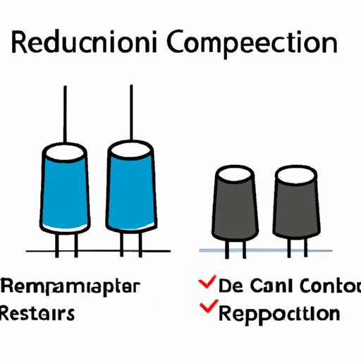
Popular models of common capacitor symbols
Popular Models of Common Capacitor Symbols
I. Introduction
Capacitors are fundamental components in electronic circuits, playing a crucial role in energy storage, filtering, and timing applications. As passive electronic devices, they store electrical energy in an electric field, allowing them to release that energy when needed. Understanding the various symbols used to represent capacitors in circuit diagrams is essential for anyone involved in electronics, from hobbyists to professional engineers. This article aims to explore common capacitor symbols, their meanings, and their significance in electronic schematics.
II. Overview of Capacitor Basics
A. What is a Capacitor?
A capacitor is a two-terminal electronic component that stores electrical energy in an electric field. It consists of two conductive plates separated by an insulating material known as a dielectric. When a voltage is applied across the plates, an electric field is created, allowing the capacitor to store energy. The primary function of a capacitor is to store and release electrical energy, making it essential in various applications, including power supply smoothing, signal coupling, and timing circuits.
B. Types of Capacitors
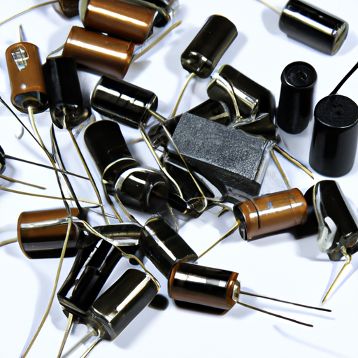
Capacitors come in various types, each with unique characteristics and applications:
1. **Electrolytic Capacitors**: These capacitors are polarized and typically used for high-capacitance applications, such as power supply filtering. They have a larger capacitance value but are sensitive to voltage polarity.
2. **Ceramic Capacitors**: Known for their stability and reliability, ceramic capacitors are non-polarized and widely used in high-frequency applications. They are available in various capacitance values and voltage ratings.
3. **Film Capacitors**: These capacitors use a thin plastic film as the dielectric. They are known for their low loss and high stability, making them suitable for audio and high-frequency applications.
4. **Tantalum Capacitors**: Tantalum capacitors are polarized and offer high capacitance in a small package. They are commonly used in compact electronic devices but require careful handling due to their sensitivity to voltage.
5. **Supercapacitors**: Also known as ultracapacitors, these devices can store a large amount of energy and are used in applications requiring rapid charge and discharge cycles, such as energy storage systems.
III. Importance of Symbols in Circuit Diagrams
A. Role of Symbols in Electronic Schematics
In electronic schematics, symbols serve as a universal language that allows engineers and technicians to communicate circuit designs effectively. Each symbol represents a specific component, making it easier to understand the function and interconnections within a circuit.
B. Standardization of Symbols for Clarity and Communication
Standardized symbols ensure clarity and consistency across different schematics, reducing the likelihood of misinterpretation. This standardization is crucial for collaboration among engineers and for the documentation of electronic designs.
C. International Standards (IEC, ANSI)
Organizations such as the International Electrotechnical Commission (IEC) and the American National Standards Institute (ANSI) have established guidelines for electronic symbols. These standards help maintain uniformity in the representation of components, including capacitors, across various industries and regions.
IV. Common Capacitor Symbols
A. Basic Capacitor Symbol
The basic capacitor symbol consists of two parallel lines representing the conductive plates, with a gap between them indicating the dielectric. This symbol is widely used in circuit diagrams to represent a generic capacitor. It is essential for understanding the basic function of capacitors in circuits.
B. Polarized Capacitor Symbol
Polarized capacitors, such as electrolytic capacitors, have a specific orientation due to their construction. The symbol for a polarized capacitor includes a curved line on one side, indicating the positive terminal. This representation is crucial for ensuring correct installation and operation, as reversing the polarity can lead to failure or damage.
C. Non-Polarized Capacitor Symbol
Non-polarized capacitors, such as ceramic and film capacitors, are represented by the same basic symbol as regular capacitors, without any additional markings. This indicates that they can be connected in either direction, making them versatile for various applications.
D. Variable Capacitor Symbol
Variable capacitors, which allow for adjustable capacitance, are represented by a similar symbol to the basic capacitor but with an additional line or arrow indicating the adjustable feature. These capacitors are commonly used in tuning circuits, such as radio receivers.
E. Tantalum Capacitor Symbol
The symbol for tantalum capacitors is similar to that of polarized capacitors, with a specific indication of the positive terminal. Tantalum capacitors are often used in applications requiring high capacitance in a compact form factor, making their correct representation in schematics essential.
F. Supercapacitor Symbol
Supercapacitors are represented by a symbol similar to that of regular capacitors but may include additional markings to indicate their unique characteristics, such as high capacitance and energy storage capabilities. Understanding this symbol is vital for applications involving energy storage and rapid discharge.
V. Specialized Capacitor Symbols
A. Capacitor with a Series Resistor
In some circuits, capacitors are used in conjunction with resistors to form specific configurations, such as RC filters. The symbol for a capacitor with a series resistor combines the standard capacitor symbol with a resistor symbol, indicating the relationship between the two components.
B. Capacitor with a Series Inductor
Similarly, capacitors can be used with inductors to create LC circuits. The symbol for a capacitor with a series inductor combines the capacitor symbol with an inductor symbol, highlighting the interaction between the two components in resonant circuits.
C. Capacitor in a Circuit with Other Components
Complex circuits may involve capacitors in conjunction with various other components, such as transistors, diodes, and integrated circuits. Understanding how to interpret these symbols in context is crucial for analyzing and designing electronic circuits effectively.
VI. Understanding Capacitor Ratings and Specifications
A. Voltage Rating
The voltage rating of a capacitor indicates the maximum voltage it can handle without breaking down. Exceeding this rating can lead to catastrophic failure, making it essential to select capacitors with appropriate voltage ratings for specific applications.
B. Capacitance Value
The capacitance value, measured in farads (F), indicates the amount of charge a capacitor can store. Different applications require different capacitance values, so understanding this specification is crucial for selecting the right capacitor.
C. Tolerance
Tolerance refers to the allowable variation in capacitance value. Capacitors are available with different tolerance levels, which can affect circuit performance. Selecting capacitors with appropriate tolerances is essential for precision applications.
D. Temperature Coefficient
The temperature coefficient indicates how a capacitor's capacitance value changes with temperature. This specification is important for applications where temperature fluctuations may occur, as it can impact circuit performance.
E. Frequency Response
Capacitors have frequency response characteristics that determine how they behave at different frequencies. Understanding these characteristics is essential for applications involving signal processing and filtering.
VII. Conclusion
Understanding capacitor symbols is vital for anyone working with electronic circuits. These symbols provide a universal language that facilitates communication and collaboration among engineers and technicians. By familiarizing oneself with the various capacitor symbols and their meanings, individuals can enhance their ability to read and interpret circuit diagrams effectively.
Capacitors play a crucial role in modern electronics, and their correct representation in schematics is essential for ensuring proper functionality. As technology continues to evolve, the importance of capacitors and their symbols will remain significant in the design and implementation of electronic systems.
VIII. References
- Suggested readings and resources for further exploration of capacitors and their symbols.
- Relevant standards and guidelines for electronic symbols, including IEC and ANSI documentation.
By understanding the popular models of common capacitor symbols, you can enhance your knowledge and skills in electronics, paving the way for successful circuit design and analysis.

