What are the comparative differences between mainstream parallel plate capacitor models?
Comparative Differences Between Mainstream Parallel Plate Capacitor Models
I. Introduction
Capacitors are fundamental components in electrical engineering, serving as energy storage devices that play a crucial role in various electronic circuits. Among the different types of capacitors, parallel plate capacitors are widely studied and utilized due to their simplicity and effectiveness. This blog post aims to explore the comparative differences between mainstream parallel plate capacitor models, shedding light on their characteristics, applications, and performance metrics.
II. Basic Principles of Parallel Plate Capacitors
A. Structure and Functionality
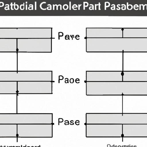
Parallel plate capacitors consist of two conductive plates separated by a dielectric material. The plates store electric charge, and the dielectric enhances the capacitor's ability to store energy by reducing the electric field between the plates. When a voltage is applied across the plates, an electric field is established, allowing the capacitor to store energy in the form of an electric field.
B. Capacitance Formula
The capacitance (C) of a parallel plate capacitor is calculated using the formula:
\[ C = \frac{\varepsilon A}{d} \]
where:
- \( C \) is the capacitance,
- \( \varepsilon \) is the permittivity of the dielectric material,
- \( A \) is the area of one of the plates, and
- \( d \) is the distance between the plates.
C. Factors Affecting Capacitance
Several factors influence the capacitance of a parallel plate capacitor, including the size of the plates, the distance between them, and the type of dielectric material used. Understanding these factors is essential for optimizing capacitor performance in various applications.
III. Overview of Mainstream Parallel Plate Capacitor Models
A. Ideal Parallel Plate Capacitor
An ideal parallel plate capacitor is a theoretical model that assumes perfect conditions: infinite plate size, no edge effects, and a uniform electric field. This model serves as a benchmark for understanding capacitor behavior and is often used in educational contexts.
1. Characteristics
- Infinite plate area
- Uniform electric field
- No dielectric losses
2. Applications
Ideal capacitors are primarily used in theoretical analyses and simulations, providing a simplified view of capacitor behavior.
B. Real-World Parallel Plate Capacitor
Real-world parallel plate capacitors account for practical limitations, such as finite plate size and edge effects. These capacitors exhibit non-ideal behaviors due to dielectric losses and other factors.
1. Characteristics
- Finite plate area
- Edge effects present
- Dielectric losses
2. Applications
Real-world capacitors are used in various electronic devices, including power supplies, filters, and timing circuits.
C. Non-Ideal Parallel Plate Capacitor
Non-ideal parallel plate capacitors consider additional complexities, such as temperature dependence, frequency response, and manufacturing variances. These capacitors provide a more accurate representation of real-world performance.
1. Characteristics
- Variability in capacitance
- Temperature and frequency dependence
- Manufacturing tolerances
2. Applications
Non-ideal capacitors are commonly found in high-frequency applications, such as RF circuits and communication devices, where performance under varying conditions is critical.
IV. Comparative Analysis of Capacitor Models
A. Capacitance Values
1. Ideal vs. Real-World
The capacitance of an ideal capacitor is straightforward to calculate, while real-world capacitors often exhibit lower capacitance values due to factors like dielectric losses and edge effects. This discrepancy can impact circuit design and performance.
2. Non-Ideal Considerations
Non-ideal capacitors may show significant variations in capacitance based on environmental conditions, making them less predictable than their ideal counterparts.
B. Dielectric Materials
1. Types of Dielectrics Used
Common dielectric materials include air, ceramic, polyester, and tantalum. Each material has unique properties that affect capacitance, voltage rating, and temperature stability.
2. Impact on Performance
The choice of dielectric material significantly influences the capacitor's performance, including its capacitance value, frequency response, and reliability. For instance, ceramic capacitors are known for their stability and low losses, making them suitable for high-frequency applications.
C. Frequency Response
1. Behavior at Different Frequencies
Capacitors exhibit different behaviors at varying frequencies. Ideal capacitors maintain a constant capacitance across frequencies, while real-world and non-ideal capacitors may experience changes in capacitance due to dielectric losses and parasitic effects.
2. Implications for Circuit Design
Understanding the frequency response of capacitors is crucial for circuit designers, as it affects the performance of filters, oscillators, and other frequency-dependent applications.
D. Temperature and Environmental Effects
1. Performance Variability
Temperature changes can significantly impact capacitor performance. Real-world and non-ideal capacitors may experience shifts in capacitance and increased leakage currents at elevated temperatures.
2. Reliability and Longevity
The reliability of capacitors is influenced by environmental factors such as humidity, temperature, and mechanical stress. Non-ideal capacitors may have shorter lifespans due to these factors, making it essential to consider operating conditions during selection.
E. Manufacturing Techniques
1. Production Methods
Capacitors are manufactured using various techniques, including film deposition, ceramic processing, and electrolytic methods. Each method affects the capacitor's characteristics and performance.
2. Cost Implications
The choice of manufacturing technique can also impact the cost of capacitors. For example, ceramic capacitors may be more expensive to produce than film capacitors, influencing their use in different applications.
V. Applications of Different Capacitor Models
A. Consumer Electronics
In consumer electronics, capacitors are used in power supplies, audio equipment, and signal processing circuits. The choice of capacitor model depends on the specific requirements of the application, such as size, cost, and performance.
B. Industrial Applications
In industrial settings, capacitors are employed in motor drives, power factor correction, and energy storage systems. Real-world and non-ideal capacitors are often preferred for their robustness and reliability.
C. Automotive and Aerospace
Capacitors play a critical role in automotive and aerospace applications, where performance under extreme conditions is essential. Non-ideal capacitors are commonly used in these sectors due to their ability to withstand varying temperatures and frequencies.
D. Research and Development
In research and development, capacitors are used in experimental setups and prototype designs. Understanding the differences between capacitor models is crucial for developing innovative technologies and improving existing systems.
VI. Conclusion
In summary, the comparative differences between mainstream parallel plate capacitor models highlight the importance of understanding their characteristics, applications, and performance metrics. While ideal capacitors serve as a useful theoretical framework, real-world and non-ideal capacitors provide the practical insights necessary for effective circuit design. As technology continues to evolve, the demand for advanced capacitor models will grow, driving innovation in materials, manufacturing techniques, and applications.
VII. References
- Academic Journals on Electrical Engineering
- Textbooks on Capacitor Theory and Applications
- Industry Reports and White Papers on Capacitor Technology
By understanding the nuances of different parallel plate capacitor models, engineers and designers can make informed decisions that enhance the performance and reliability of their electronic systems.

