What components and modules does the Crane Resistor Wiring Diagram contain?
What Components and Modules Does the Crane Resistor Wiring Diagram Contain?
I. Introduction
Crane systems play a pivotal role in various industrial applications, from construction sites to manufacturing plants. These heavy-duty machines are designed to lift and move materials efficiently, making them indispensable in modern industry. However, the complexity of crane operations necessitates a thorough understanding of their electrical systems, particularly the resistor wiring diagrams that govern their functionality.
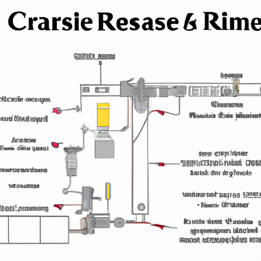
A resistor wiring diagram is a schematic representation that outlines the electrical connections and components involved in a crane's operation. This article aims to explore the various components and modules found in a crane resistor wiring diagram, shedding light on their functions and importance in ensuring safe and efficient crane operations.
II. Understanding Crane Resistor Wiring Diagrams
A. Definition of a Wiring Diagram
A wiring diagram is a visual representation of an electrical circuit. It illustrates how different components are interconnected, providing a clear roadmap for understanding the flow of electricity within a system. In the context of cranes, wiring diagrams are essential for troubleshooting, maintenance, and ensuring compliance with safety standards.
B. Importance of Wiring Diagrams in Crane Operation and Maintenance
Wiring diagrams serve as a crucial tool for technicians and engineers. They help identify potential issues, facilitate repairs, and ensure that all components are functioning correctly. A well-structured wiring diagram can significantly reduce downtime and enhance the overall efficiency of crane operations.
C. Basic Elements of a Wiring Diagram
A typical wiring diagram includes symbols representing various electrical components, lines indicating connections, and annotations that provide additional information. Understanding these elements is vital for anyone working with crane electrical systems.
III. Key Components of Crane Resistor Wiring Diagrams
A. Resistors
1. Function and Purpose in Crane Systems
Resistors are fundamental components in electrical circuits, used to limit current flow and manage voltage levels. In crane systems, resistors play a critical role in controlling the speed of motors and protecting sensitive components from excessive current.
2. Types of Resistors Used in Cranes
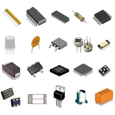
Common types of resistors found in crane systems include wire-wound resistors, carbon film resistors, and power resistors. Each type has specific characteristics that make it suitable for different applications within the crane's electrical system.
B. Contactors
1. Role in Controlling Electrical Circuits
Contactors are electrically operated switches that control the flow of electricity to various components in a crane. They are essential for starting and stopping motors, as well as for switching between different operational modes.
2. Types of Contactors Commonly Used in Cranes
There are several types of contactors, including AC contactors, DC contactors, and overload relays. Each type is designed to handle specific voltage and current ratings, ensuring reliable operation in demanding environments.
C. Relays
1. Definition and Function
Relays are electromagnetic switches that open or close circuits based on input signals. They are used to control high-power devices with low-power signals, making them essential for crane operations.
2. Importance in Safety and Control Systems
Relays enhance the safety and reliability of crane systems by providing fail-safe mechanisms. For instance, they can disconnect power in the event of a fault, preventing damage to equipment and ensuring operator safety.
D. Switches
1. Types of Switches Used in Crane Operations
Switches are used to control the flow of electricity in crane systems. Common types include toggle switches, push-button switches, and limit switches, each serving specific functions in the operation of the crane.
2. Their Role in Controlling Power Flow
Switches allow operators to start, stop, and adjust the operation of various components, providing essential control over the crane's functions.
E. Fuses and Circuit Breakers
1. Importance in Protecting Electrical Circuits
Fuses and circuit breakers are critical for protecting electrical circuits from overloads and short circuits. They act as safety devices that interrupt the flow of electricity when a fault occurs.
2. Types and Specifications Relevant to Cranes
Fuses come in various types, including cartridge fuses and blade fuses, while circuit breakers can be thermal or magnetic. Selecting the appropriate type and rating is crucial for ensuring the safety and reliability of crane operations.
F. Power Supply Units
1. Overview of Power Supply Requirements for Cranes
Power supply units (PSUs) convert electrical energy from the grid into usable power for crane systems. They must provide stable voltage and current to ensure the proper functioning of all components.
2. Types of Power Supply Units Used
Common types of PSUs include linear power supplies, switching power supplies, and uninterruptible power supplies (UPS). Each type has its advantages and is chosen based on the specific requirements of the crane system.
G. Motors
1. Types of Motors Used in Cranes
Crane systems typically use AC and DC motors, each with distinct characteristics. AC motors are favored for their efficiency and durability, while DC motors offer precise control over speed and torque.
2. Their Integration into the Wiring Diagram
Motors are integrated into the wiring diagram, showing their connections to power sources, control devices, and other components. Understanding this integration is essential for troubleshooting and maintenance.
H. Control Panels
1. Overview of Control Panels in Crane Systems
Control panels house the various controls and indicators necessary for operating a crane. They provide a centralized location for monitoring and managing the crane's functions.
2. Components Found Within Control Panels
Control panels typically include switches, indicators, relays, and circuit breakers. Each component plays a vital role in ensuring the safe and efficient operation of the crane.
IV. Modules in Crane Resistor Wiring Diagrams
A. Control Modules
1. Definition and Purpose
Control modules are specialized devices that manage the operation of various components within a crane system. They process input signals and send commands to actuate motors, switches, and other devices.
2. Types of Control Modules Used in Cranes
Common types of control modules include programmable logic controllers (PLCs) and microcontrollers. These devices offer flexibility and programmability, allowing for complex control strategies.
B. Feedback Modules
1. Importance of Feedback in Crane Operations
Feedback modules provide real-time data on the crane's performance, such as position, speed, and load. This information is crucial for ensuring safe and efficient operations.
2. Types of Feedback Modules
Common feedback modules include encoders, limit switches, and load cells. Each type provides specific data that helps operators make informed decisions during crane operations.
C. Communication Modules
1. Role in Data Transmission and Control
Communication modules facilitate data exchange between different components of the crane system. They enable remote monitoring and control, enhancing operational efficiency.
2. Types of Communication Modules Used
Common communication modules include Ethernet modules, wireless communication devices, and fieldbus systems. These technologies allow for seamless integration of various components.
D. Safety Modules
1. Overview of Safety Features in Crane Systems
Safety modules are designed to monitor and control safety-critical functions within a crane system. They ensure that the crane operates within safe parameters and can respond to emergencies.
2. Types of Safety Modules and Their Functions
Safety modules may include emergency stop circuits, safety relays, and monitoring systems. These components work together to prevent accidents and protect both operators and equipment.
V. Interconnections and Layout
A. How Components Are Interconnected in a Wiring Diagram
In a wiring diagram, components are interconnected using lines that represent electrical connections. Understanding these interconnections is essential for troubleshooting and maintenance.
B. Importance of Layout for Troubleshooting and Maintenance
A well-organized layout in a wiring diagram simplifies troubleshooting by allowing technicians to quickly identify and isolate issues. Clear labeling and logical arrangement of components enhance the effectiveness of the diagram.
C. Common Practices for Creating Effective Wiring Diagrams
Best practices for creating wiring diagrams include using standardized symbols, maintaining clarity, and ensuring accuracy. Following these guidelines helps ensure that the diagram serves its intended purpose effectively.
VI. Practical Applications and Case Studies
A. Real-World Examples of Crane Resistor Wiring Diagrams
Examining real-world examples of crane resistor wiring diagrams can provide valuable insights into their practical applications. These diagrams illustrate how various components work together to achieve specific operational goals.
B. Analysis of Specific Components in Action
Analyzing specific components within the context of a wiring diagram can help identify best practices and potential pitfalls. Understanding how each component interacts with others is crucial for optimizing crane performance.
C. Lessons Learned from Practical Applications
Case studies can reveal important lessons about the design, implementation, and maintenance of crane electrical systems. These insights can inform future projects and improve overall safety and efficiency.
VII. Conclusion
Understanding crane resistor wiring diagrams is essential for anyone involved in the operation, maintenance, or design of crane systems. By familiarizing oneself with the various components and modules, operators and technicians can enhance safety, efficiency, and reliability in crane operations.
As the industry continues to evolve, further study and understanding of electrical systems in cranes will be crucial. Embracing this knowledge will not only improve operational performance but also contribute to a safer working environment for all involved.
VIII. References
A comprehensive list of resources for further reading on crane systems and electrical wiring diagrams can be found in industry publications, textbooks, and online platforms. Engaging with these materials will deepen your understanding and enhance your expertise in this critical field.


